Aquatherm Maintenance Plan
202004A – AQTTB
Date Issued: 23 April 2020
This document provides guidance and recommendations regarding maintenance of piping systems after initial installation, testing and commissioning. Much of this information is generally applicable to all pressure piping systems, while some items are specific to Aquatherm piping. The focus of this Maintenance Plan is on plumbing and mechanical piping, but it may also be used for other types of piping systems.
-
To properly monitor system conditions and any abnormal operation, it is recommended that a digital data acquisition system (DAQ) be utilized. The system should provide notification to appropriate facilities or service personnel in the event of abnormal/upset conditions. The following parameters should be measured hourly for routine operation, with the capability for more frequent monitoring to detect abnormal conditions.
-
pH;
- Note: Changes in pH may indicate degradation of additives due to excessive temperature fluctuations in hot water systems.
- Total dissolved gas (TDG) or dissolved oxygen (DO)
-
Turbidity
- Note: Changes in turbidity levels should be investigated to determine if this is related to suspended solids or air bubbles in the flow stream.
- Temperature
- Pressure
- Flow rate
- Total copper and iron concentration in the water (indication of erosion/corrosion of metal piping/tubing or components in the system)
-
Leak monitoring, especially in riser shafts/areas, mechanical rooms, and other locations where piping is subjected to the higher temperature and pressure conditions.
- Note: Leak monitoring should be done via an analog device or at a higher sampling frequency than once per hour to ensure that any leaks are detected as quickly as possible.
-
pH;
-
The design and installation of the Aquatherm piping was carried out based on anticipated operating temperatures and pressures. The piping chosen for the project was chosen to accommodate these parameters. Verify that the system is still operating at the original design conditions. Changes in these conditions such as higher temperature may indicate other system issues that need to be addressed. If the temperature or pressure of this Aquatherm piping system is required to change, please notify Aquatherm Engineering (engineering@aquatherm.com or call (801) 805-6657) to ensure that the proposed changes are within the limits of the installed piping.
Verify the following:
- Temperature limits and gauges/sensors working properly and reading within design temperature range.
- Pressure limits and gauges/sensors working properly and reading within design pressure range.
-
Pump operation in accordance with original design program (VFD operation, history, pump maintenance).
- Particular attention should be paid to short-cycling, possible deadhead (no flow) situations such as valve closures or low suction head resulting in starved pump, and flow/temperature/pressure data during any of these events.
-
Check surge/expansion/bladder tank pressures are correct, and that the system maximum operating pressure does not exceed tank ratings and set pressures.
- Check the surge/expansion/bladder tanks to ensure they are not waterlogged (water on the air side of bladder/diaphragm). Follow the manufacturers’ instructions for recommended maintenance and replacement schedule.
- Check air release valves for proper operation.
- Verify flow control/balancing valves (e.g. circuit setters) are functional and set properly per original balance report.
- Verify pressure regulating/reducing valves (PRVs) are at correct setpoints per design specifications and functioning properly.
-
UV Protection:
- Evaluate the system and verify the location of any piping exposed to UV, either by direct sunlight or through windows that do not filter UV.
- Verify the UV protective coating, paint, wrap, insulation, or other means of protection is intact for all exposed piping.
- Inspect exposed piping, valves and insulation for any indication of slow leaks.
- Review maintenance/service call logs and verify that any repairs or adjustments made since the last inspection are still in place and operating correctly.
-
The design and installation of the Aquatherm piping was carried out with the anticipation that certain chemicals would be in the water or chemicals themselves would be carried directly by the piping. The piping chosen for the project was chosen based on these parameters. Verify that the fluid being transported has not changed from the original design. If the chemistry of the water or chemical carried by this Aquatherm piping system is required to change, please notify Aquatherm Engineering (engineering@aquatherm.com or call (801) 805-6657) to ensure that the proposed changes are within the limits of the installed piping.
- Verify chemical additive concentrations are correct (e.g., corrosion inhibitors, antifreeze)
- Verify the system has air release valves installed at the high points in each zone and are still functioning properly.
- Verify the speed selection on multi-speed pumps are correctly set per the original system testing/commissioning settings.
- If there are flanged connections or butterfly valve connections in the Aquatherm system, please follow the guidelines noted in Technical Bulletin 201405B – AQTTB – Flanges and Butterfly Valve Installation Guidelines. Please note that flange bolts and nuts can loosen over time from expansion and contraction and may need to be periodically re-tightened. It is recommended these connections/bolts be checked on a regular basis to ensure that loosening has not occurred.
-
The following maintenance guidelines for valves must be followed.
- The valve manufacturer recommends that the valve be cleaned periodically depending on external conditions.
- Clean only with a damp cloth. Do not use chemicals that will corrode the housing or the seals.
-
The valve should be checked for functionality (exercised) at least quarterly. The following are suggestions for checking the valve for functionality.
- Verify the direction for turning the valve.
- Verify that the valve is installed correctly. See Aquatherm Technical Bulletin No.201609A – AQTTB – Aquatherm Polypropylene Ball Valve Installation Notes.
- Close the valve slowly.
- Open the valve slowly.
- Repeat the open/close cycle at least three (3) times.
- It is recommended that the customer add the Aquatherm piping system and piping equipment into their structured Facility Inspection and Equipment Maintenance Plans.
-
Aquatherm piping is freeze-tolerant, meaning that it should not rupture if accidentally allowed to freeze, provided it can expand during the freezing process. The pipe will rupture and break if exposed to repeated freeze/thaw cycles. Please refer to Aquatherm Technical Bulletin 201606B – AQTTB – Freeze Protection of Aquatherm Piping. Any piping exhibiting deformation or damage due to freezing should be replaced.
- If heat tracing is used to keep pipe/water from freezing, verify that the heat trace thermostat and other components are working properly. Follow the manufacturers’ recommendations for installation, operation, maintenance and replacement schedule. For additional information, see Aquatherm Technical Bulletin 201503A-AQTTB1 Heat Tracing Aquatherm Pipe.
- Verify that the Aquatherm True Union Ball Valves are not subjected to temperatures and pressures higher than those listed in Table 2 of the Aquatherm Ball Valves Notice dated 3 November 2023, and in the Design and Planning Guide, page 3.03.
Supplementary instructions regarding ball valves
- The descriptions and part numbers for the valves addressed in these supplementary instructions are:
- True Union Polypropylene Ball Valves, ½ – 2 in., 1090020052 – 1090063057, 1090020020-1090063025
- True Union Polypropylene Ball Valve, 2 ½-in., 1090075051
- Polypropylene Ball Valve, ISO flange connection, 3 – 6 in., 9790041802, 04, 07
-
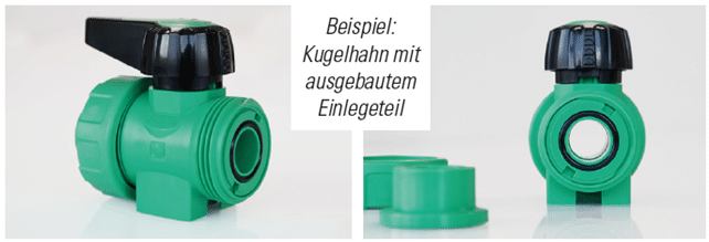
Seat carrier/retainer – The following instructions are applicable to the True Union Polypropylene Ball Valves, ½ – 2 in.
- The seat carrier/retainer must be prevented from rotating when removing the union connection if the system is under pressure.
- When installing and using the ball valve as an end cap/fitting, the handle must point to the open end (not connected) of the valve when the valve is in the open position.
- When using the ball valve as an end cap during leak testing, the valve may not seal air tight. In this case, hydrostatic testing should be conducted.
-
Open/Close Positions – The following are applicable to all valves:
-
Handle aligned with pipe direction, valve is in open position.
- When in the open position, the handle should be pointing in the direction of flow.
- Handle at a right angle to the pipe direction, valve is in closed position.
- These are quarter-turn valves, meaning that the handle only moves ¼-turn to fully open or close. Turning it clockwise will close the valve and turning it counter-clockwise will open the valve.
-
Handle aligned with pipe direction, valve is in open position.
-
Bolts and gaskets – Applicable to PP ball valve, ISO flange connection, 3 – 6 in.:
-
The bolts connecting the large Aquatherm ball valves to the Aquatherm piping system are metric. Any replacement bolts will need to be metric as well. The following table shows the sizes of the bolts required for each valve.
Table S1 – Bolt sizes for flange valves
Part No. Valve nominal size Bolt sizes 9790041802 3 in. – 90 mm M16 x 60 mm with M16 washers 9790041804 3 ½ to 4 in. – 110 to 125 mm M16 x 60 mm with M16 washers 9790041807 6 in. – 160 mm M20 x 90 mm with M20 washers - The gaskets used to seal the flanged connections for these valves to the pipeline are metric or ISO pattern. They can be ordered from Aquatherm or can be made locally. For required dimensions please refer to Aquatherm Technical Bulletin 201403A – AQTTB – Large Diameter Ball Valve Clarifications.
- Bolt/gasket kits are available from Aquatherm distributors for the 3-6 in. (90-160mm) valves.
-
The bolts connecting the large Aquatherm ball valves to the Aquatherm piping system are metric. Any replacement bolts will need to be metric as well. The following table shows the sizes of the bolts required for each valve.
-
Maintenance of Polypropylene and brass ball valves
WARNING! Before start of work, determine any hazards associated with the system such as the fluid being transported, temperature, pressure, and any risk of exposure to these or other conditions. Failure to follow appropriate safety precautions may lead to serious injury or death. Wear personal protective equipment (PPE) applicable to the potential hazards. - It is recommended that the system be brought to ambient pressure and temperature, and preferably drained, before any maintenance is conducted on the valve involving removal of any valve components or union connections.
- ATTENTION: Even after draining the system, there may still be some residual fluid inside the valve.
- Valves conveying hazardous materials/fluids must be decontaminated before starting any work on the valve.
- Properly collect and dispose of any residual hazardous materials/fluids.
-
The following minimum maintenance is required for the valves, at least four (4) times per year, or after any significant changes to the system, including, but not limited to operating temperature, operating pressure, or type of fluid being conveyed.
- Ensure the union nuts are tight and there are no leaks. Tighten the union nuts by hand. An additional 1/8 turn of the union nut may be done if needed, by using a strap wrench on the nut while securing the valve in place.
-
Ensure the flange bolts are tight and there are no leaks. Tighten the flange bolts to the torque in Table S2.
Table S2 – Bolt torque for flange valves
Part No.1 Valve nominal size Bolt torque 9790041802 3 in. – 90 mm 40 Nm (29 ft·lb) 9790041804 3 ½ to 4 in. – 110 to 125 mm 50 Nm (37 ft·lb) 9790041807 6 in. – 160 mm 60 Nm (44 ft·lb) - Exercise the valve – Operate the valve from full open to full close position for at least three (3) cycles.
-
Valve leaks or damage – Leaks or valve damage may occur due to excessive forces on the valve from improper mounting and pipe supports, incorrect pipe length, using the union connection to “pull” the connection together, bending loads, thermal expansion and contraction, or incorrect/excessive movement of the valve handle. Verify the following as part of the valve maintenance:
- Proper piping supports to ensure no tensile or compressive force.
- Proper piping supports to ensure no bending moments/loads.
- Compensation for thermal expansion/contraction to avoid any stresses on the valve.
-
The following minimum maintenance is required annually and also recommended whenever the system is shut down and accessible for maintenance.
- Verify that both O-rings, and the internal seals are free from any foreign material, contaminants, or other materials that may affect the fluid-tight seal of the valve.
- If the O-rings or seals show any evidence of degradation or permanent set, replace them with new components and evaluate the system to determine if alternative materials should be used based on operating conditions and fluid being transported.
- Once the system is ready to put back into service, verify tightness and valve operation per S5.E
WARNING!
Leaks due to improper system design or installation may result in exposure to hazardous fluids resulting in serious injury or death. This may also require hazardous materials handling and hazardous spill response.
Revisions
- 28 Oct 2021 – Revised part numbers
- 29 January 2024 – Green Pipe Revisions, updates, new part numbers