Aquatherm Ball Valve Installation Notes
201609A – AQTTB
Date Issued: 9 September 2016
Aquatherm polypropylene ball valves have been used on projects for many years. They are a reliable ball valve, easy to install and easy to use.
The following information is meant to help install the ball valves correctly. This applies to the polypropylene ball valves numbers 0041488 -00414004 as well as the large ball valves with part numbers 0041802 – 00418074.
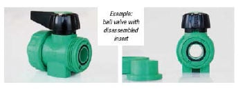
- Refer to the photos below. The spanner nut must be checked to ensure that it has not loosened in the valve during shipment.
- Upon installation of the valve as an end of the line fitting, the spanner nut must be pointed upstream toward the flow of the system. Otherwise, if the spanner nut has become loosened, the valve can leak or come apart under the pressure of the system when the union nut is removed or loosened.
Preparation:
- Be sure to follow all local, state and national codes and standards when installing the valve.
- The ball valve must always be in the open position when installing the valve.
- Ensure the valve is to be installed in a location and supported such that axial loads, bending loads, and stress from thermal expansion/contraction will not be acting on the valve.
- Before installing the valve operate the valve open and closed to ensure that the valve operates properly. Check the valve for any shipping damage that may have occurred.
Installation:
- Correctly cut the pipe ends to the proper length and prepare them for connection to the valve.
- The ball valve must always be installed with the ball fully open.
- The handle should point downstream, in the flow direction when installed. The valves do not have a required flow direction in terms of flow characteristics, but installing with the handle in the flow direction will help ensure the internal components do not allow leakage if the downstream side is open to atmosphere while the upstream side is pressurized.
- Loosen union nuts and pull them over the ends of the pipe. Properly connect the socket or spigot ends with the pipeline ends. Insert the valve between the pipeline ends and connect using the union nuts.
- Verify that the O-rings are properly positioned in the grooves.
- Tighten the union nuts only hand tight. Excessive torque might result in leakage.
Pressure Testing:
- 1. Use only a neutral medium, such as compressed air, nitrogen and water, for testing. However, compressed air can pass by the ball in a closed valve. It is best to test with the valve open, if possible, or with water.2
- Ensure that the test pressure does not exceed those proscribed in the Aquatherm pressure test.
- Also observe the permissible pressure of other system components.
Over tightening of the union nuts can cause too much pressure on the seat carrier against the ball portion of the valve making it difficult to operate the valve. Tighten the union nut only as indicated above.
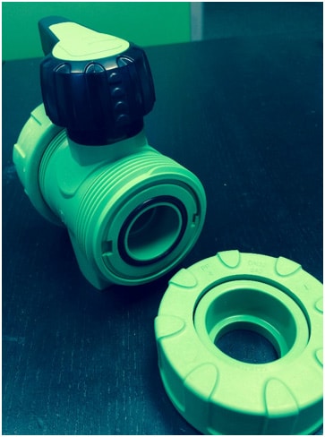
Figure 1: Aquatherm Polypropylene Ball valve showing access to the valve ball and internal parts. It is suggested to install the valve with flow in the direction of the arrow.
As noted in the photo, the direction of the flow is important for future access to the system. If the valve is installed in the opposite direction, the valve seat carrier/ball access spanner nut can become loosened. When removing the valve union nut, the valve interior parts can be dumped out due to the system pressure resulting in the operator getting wet, possible personal injury, and possibly causing property damage. In some cases, the ball can be completely blown out by the system pressure.
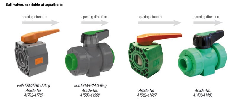
It is important to remember that all the ball valves offered by Aquatherm should be installed with the valve handle indicating the direction of flow, especially if the valve is installed as an end of the line fitting.3
Revisions
- Revised 9 Feb 2018
- Revised 2 March 2018
- Revised 22 May 2018
- Revised 19 Oct 2021 – revised part numbers